I purchased the 2010 screenset for Mach 3 because it has some nice auto tool change features I want to use.
I have some stuff I did in Meshcam that requires a tool change for finish and pencil cuts and I want to be able to accurately zero the the axis reference after changing tools. The 2010 screenset provides the ability to use home switches and a fixed plate and a moveable plate which are wired to the probe input of Mach 3.
The software routines then automatically move the gantry and recalculate the references by probing to the fixed and moveable plates.
I was disappointed to find that the Bosch Pony Laminate router does not have any place in which to electrically locate the bit. The bit seems to be isolated from all of the metal components on the router so I will have to use a ground wire with an alligator clip to clip onto the bit once the spindle stops for an M6 command.
The tool change routines will do their thing and then before I continue cutting, I will remove the alligator clip and restart the spindle.
Saturday, January 29, 2011
Friday, January 28, 2011
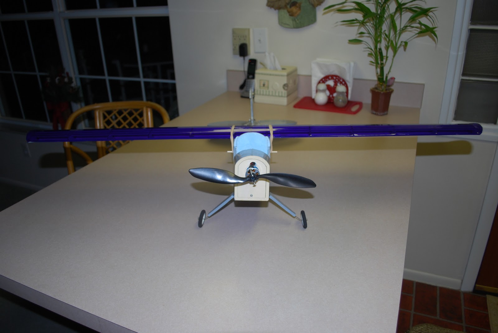
EO Cub Maiden
Did the maiden flight this morning. Typical cub tendencies to tip stall. Needed to change the wing incidence just to be able to fly it at all. One degree incidence was too much. Flew better after lowering it back to zero.
Need to add a bit of down thrust to the motor and then try it again. Not sure I am going to like this plane much. We'll see...
Need to add a bit of down thrust to the motor and then try it again. Not sure I am going to like this plane much. We'll see...
Thursday, January 27, 2011
Ready for Maiden... EO-Cub
Still have a few things to add, windshield, cowl, lettering, etc.
But will add those after we see how she flys tomorrow.


But will add those after we see how she flys tomorrow.


Wednesday, January 26, 2011
Planet-CNC board backlash correction works now
Today was another step forward. The Planet-CNC software backlash compensation has been fixed.
Andrej sent me a link to the beta for testing and I was happy to be able to report that it is working as well as Mach 3.
Way to go Andrej!!!
Circle on left cut with Mach 3... Circle on right cut with Planet-CNC beta. Both are correcting for .014" of backlash in my Phlatprinter \\\.

Andrej sent me a link to the beta for testing and I was happy to be able to report that it is working as well as Mach 3.
Way to go Andrej!!!
Circle on left cut with Mach 3... Circle on right cut with Planet-CNC beta. Both are correcting for .014" of backlash in my Phlatprinter \\\.

Tuesday, January 25, 2011
Cutting out a FFF fuse for the Clark Y Wing
Spent today cutting out FFF for the Balsa Clark Y Wing.


I drop in now and again to see what is going on in the chat log at the Phlatforum. Still seeing guys having problems with the Easy CNC board. It is such a piece of junk, has been since day 1. Mark says it is all better now, but from what I see, it is still a piece of junk. For the same money they could have a decent controller from Probotixs or spend a few dollars more and get the Gecko G540 like I have.
Anyway, that's just my 2 cents opinion.
Sunday, January 23, 2011
Balsa Cut Clark Y Wing
Cut out a Clark Y Airfoil wing for the EO_Cub now that Phlatty Freddy is working.
So nice to actually be cutting some projects instead of Fiddling with Finicky Freddy.
The wingspan is 40" with a chord of 7 1/2" and takes 2 sheets of 6" wide 1/8" thick balsa, 1 sheet of 4" wide 1/16" balsa and one 1/8 dowel rod.


So nice to actually be cutting some projects instead of Fiddling with Finicky Freddy.
The wingspan is 40" with a chord of 7 1/2" and takes 2 sheets of 6" wide 1/8" thick balsa, 1 sheet of 4" wide 1/16" balsa and one 1/8 dowel rod.


Friday, January 21, 2011
Flash's Phlatprinter Video Tour
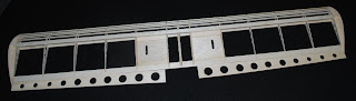
Today I cut out the EO-Cub Balsa wing which is what I consider the pinnacle of success.
This wing is 36" long along the X axis and presents a severe challenge for the machine since it has matching indents along both sides of the parts, tabs and slots that all must match up perfectly in order to assemble the wing.
With the addition of the new guides and some careful preparation, these parts came out flawlessly.
By careful preparation, I mean that the 6" strips of balsa need to be planed down to exactly 6" or 5.95 so that both sides are exactly parallel. This was easily done by dropping a burr bit down past the depth of the balsa and bringing the Y axis in to just shave a small amount of balsa as it was fed into the rollers and kept butted up against the opposite edge. Then once that was done, I could place the opposite guide rail in place and secure it so that there was zero side to side movement the entire length of balsa.
After sweet success, I decided to get out the video camera and do a video tour of all the mods I have made.
I added one more mod after shooting the video, and that was a delrin plate to hold the Z axis bearing in position. I had that on my list of things to do, but it had slipped to the wayside.

So if you have 23 minutes to spare, check out the video on youtube...


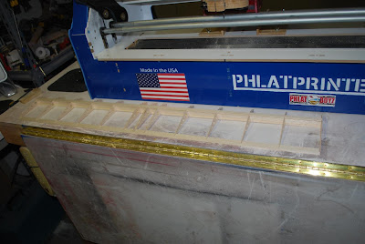
Balsa Skew Arrester Completed
Finished cutting out and installing the Balsa Skew Arrester today.
I could add a few more Tee nuts to allow wider materials to be used, but most of the balsa I will be cutting will range from 3" to 6" in width, so this worked out perfect.
I use an angle square which I got from Home Depot to square up one guide and then butt the balsa up to it and bring the second guide up to the balsa and lock the guides down with the thumb screws.
100% accurate tracking now, so I can now process my Balsa pieces without worry of it skewing out of bounds or misaligning tabs and slots over the 40 inches or so of Balsa.

Thursday, January 20, 2011
Guide Rails for Balsa
Today, I did a little R/C sailboating and went flying. Weather was just too nice not to take advantage of it.
Getting out lets me clear my head and got me to thinking about how to implement guide rails on my Phlatprinter \\\ for cutting Balsa where tracking is critical and there is no room for skew of any kind.
While I can track FFF perfectly now, put a sheet of Balsa on it and if the pressure rollers are not just exactly exerting the same force on both sides, you will get skew, be it ever so slight.
I had already experimented with clamping a temporary guide rail in place and knew that it worked to eliminate any small tracking errors associated with the pressure rollers being uneven, so I just needed to think of a way to do something more permanent.
The idea came to me on the way home, so I stopped by my local hardware store and picked up some 8/32 thumb screws, 8/32 tee nuts and another sheet of 1/4" MDF.
I drew up a set of guide rails in Sketchup and will cut them out tomorrow, drill 4 holes in the top plate to mount the tee nuts and I should have a nice set of adjustable guide rails for locking Balsa into position.

Wednesday, January 19, 2011
Locked Down and Cutting Like a Pro
It has been a long hard road, but I can now say that my Phlatprinter \\\ is cutting the way that I had expected it to from the beginning, this after a month and a half of daily trials and tribulations dealing with its finicky behaviours.
Today I buttoned up the machine and put the covers back on and retested my normal group of test files. Circles are once again circles and tracking is right on the money with both foam and MDF. I still have a few more tests to perform, but from what I am seeing, I don't think there will be any more surprises.
During all the recent activity, I had managed to break my two best 1/32" end mills. I went to Skycraft to get some replacements today only to find out that a group of folks had bought every box of the assorted sizes of bits. All that was available were a bunch of small drill bits, so it looks like I will have to order some replacements before I can complete all my tests and cut out my Balsa project.
In the coming days, if time permits, I would like to review what I have learned over the past two months and recap what it took to make my Phlatprinter \\\ perform as well as I my expectations.
I would even like to do a video showing the various areas I had to modify to get where I am today and to show some of the tests I have used during this time which have been instrumental in solving the puzzle.
I continue to see posts on the forum which indicate the same problems that I had are prevalent in other machines. Some are going it alone or waiting for new rollers to fix all their problems, but the fact is, there are many contributing factors and the only way to get one of these machines to perform at its best, is to attack it on all its fronts.
Some may not even realize they have issues because all they care about is cutting out a foam plane in which accuracy down to a 1/16" of inch is not even noticed. But there will come a day when they will need that accuracy, and it may or may not be there.
Showing that you can cut 10" circles does not mean a machine is cutting accurately. Try cutting a 1/4" hole for a landing gear screw or a 36 to 48" strip of material with slots and tabs that has to line up with matching parts cut on the X axis and then you will know whether or not that you have a perfectly tuned machine.
Tuesday, January 18, 2011
The Skew is gone, Maybe
Had to get away, go have a nice meal and come back with a fresh set of eyes.
Seems I had forgotten to fasten the right pressure roller spring after having it off to gain better access to the stepper motor.
Also, the front right roller had slipped down and was not where it belongs.
After correcting these two items, I ran a sheet of MDF thru the tracking code (air cuts) and it returned precisely where it started with the bit going perfectly back into the 1/32" hole it originated from.
Finally, at last, I have gotten the skew out... or have I.
Next, I put in a sheet of 3/4" foam board I often use for testing and as a sacrificial board for carrying balsa.
Ran the same test and observed about 1/16" of skew and not returning quite back to home.
The nice thing about using MDF is that it is stable. It rides on top of the rollers, has little or no drag when it traverses back and forth and gives a more true representation of any tracking problems. The downside is that in bigger sheets, it is much heavier and requires a good support table for longer lengths. But if it tracks straight, I can see where this could be the answer for cutting the 36" lengths of Balsa that need to track perfectly.
It is getting late, I am tired, but I have some limited success so I will leave it at that for now and come back tomorrow to do some more exhaustive testing. I need to try a sheet of 1/4" FFF to see how it compares with the MDF in regards to tracking.
Skew and Tracking Adjuster Installed
With the help of John Bernard and his working CNC machine, I was able to take my Sketchup plans to his house and cut out a new MDF roller support panel and the adjustable end caps which should allow me to adjust out the skew easily and resolve the tracking problem once and for all if it is what I suspect it is.
I installed the completed assembly this afternoon and adjusted the roller height and set the two rollers precisely the same distance apart using a digital caliper.
I observed the skew with just one 36" air cut pass moving 3/4" Blue foam thru the machine.
It is about a 1/16" with the bit returning home to the left of where it originated. This is the same results I have been seeing pretty much most of the time.
With a base established, I ran the adjustment out to spread the rollers apart further on the left side of the machine thinking this should skew the material like a belt sander would do and move the material to the right.
To my disappointment, this did not happen. The skew remained the same.
I then opened the rollers so there was about 1/4" difference in the the parallel of the two rollers and again, the results stayed the same.
I then moved the rollers in a 1/4" and no change in the material movement, still approximately 1/16" to the left of the origination point.
Both rollers are within a few thousands of an inch of being the same height on both sides.
I then ran the same test holding the pressure roller up off the right side and still no affect on the outcome.
Now I am totally baffled...
The adjustment mod worked like a charm as far as being able to adjust the rollers, but the expected results are not anywhere close to what I thought they would be.
I am running out of ideas to try.
The rollers have been shimmed, the hex rods are centered, new pulleys have been installed and centered. Whatever is causing this is still an unknown.
In my quest for answers, I have read that there is a lateral motion applied to a turning roller. Maybe it is just physics and there is nothing more that can be done to completely eliminate it.
I will have to regroup and think about this some more. I may have hit a dead end.

Monday, January 17, 2011
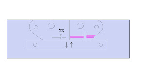
An Idea for an Adjustable Skew Plate
To make the skew adjustable, we would have to open up the opening in the MDF backplate slightly to allow one roller to be adjustable left and right as well as up and down.
A second piece of MDF would be used to hold the adjustable parts in position and let it serve the function the one piece is now doing.
The adjustable parts would have to have two halves in order to capture an adjustment screw in between them. The idea being you put the screw in place and then glue the two halves together and the screw then cannot be removed but it can supply pressure left and right on a nut which pushes and pulls the back roller in and out in relation to the fixed roller which can only move up and down.
You still have to use bolts like you have now to lock it down once adjusted, but it would make it easier to make fine adjustments a quarter turn at a time by loosening just one bolt.
The idea being that you use the bottom adjuster to get the height of the two rollers even and then that plate serves as a resting block for the moveable piece which adjusts the in and out which corrects for the skew.


Sunday, January 16, 2011
Dealing With Backlash
Okay, today I will talk about backlash, the final chapter in getting accurate cuts on the Phlatprinter \\\.
I have been observing the chat sessions on the Phlatforum and also the discussions which some are posting.
Seems there are a number of folks who cannot cut circles that are round. They tend to come out oblong. This includes my machine as well. It is the reason I have been unable to cut my EO-Cub Balsa wing parts and have them align with one another.
In my last post I talked about backlash and how to measure it. In this post, I will talk about how to get rid of it.
For those with the Planet-CNC board, I am sorry, but you are out of luck here. What is needed to correct the problem is a backlash adjustment in the software and it is disabled in the Planet-CNC code.
For those of you with parallel ports and Mach 3, there is a solution.
I found a very helpful link while searching for answers to the backlash problem and this morning, I borrowed my wifes computer (the only one in the house that still has a parallel port) and hooked it up to my Phlatprinter \\\ to see if the information I had gleaned from the link would help me with my backlash.
Turns out the guy was spot on the money! So rather than me repeat what he is saying, check it out for yourself... http://www.hossmachine.info/forum/yaf_postst6_Mach-3-Backlash-Compensation.aspx.
There are two places in Mach 3 that you have to setup. It is very simple to do and it works!
I had measured my backlash as .024 and that is a lot of backlash. It will show up with tab and slots not aligning as well as circles that are oblong
I have emailed Andrej asking him when backlash will be fixed in the Planet-CNC code but as yet, I have not received a reply. I would rather not have to buy another computer for the shop and revert back to Mach 3, but it may be the only choice left.
Friday, January 14, 2011
Skew and Backlash - Multiple Issues and a New Modification
Turns out I was still getting skew after buttoning up my machine, and the problem seems to point to the fact that the alignment of the drive rollers is extremely critical even to the point where the amount of tension applied to the X axis stepper belt being tightened affects it.
As the stepper motor is adjusted to take out the slack in the belt, it pulls the two rollers closer together which causes them to no longer be parallel with one another.
Using the Belt Sander example in which adjusting the belt sanders roller causes the sandpaper to skew left or right, the same principle applies here.
I fashioned a new end cap adjuster for the left side which split the adjustment plate into two pieces. John added some angle brackets for finer adjustment.

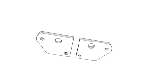
I drew it up in sketchup and cut it out, but did not actually end up using the holes I had provided along the bottom. I just used the existing bolts and tightened it down and it is holding just fine.
I tried measuring the distance between rollers on both ends to set them exactly the same distance apart on both ends, but I still ended up with skew present. I discovered that if the bit returns to the left of the origination hole, you just need to spread the left end of the rollers apart a bit more and that will move the material back to the right. It only takes a few thousandths, maybe .030 (1/32") to effect a big change, so I loosened the bolt very slightly and just tapped on the one roller to move it in very small increments.
I should also mention, that I had to enlarge the opening (for the hex shaft) on the far side of the left support panel (the one closest to the back of the machine) to give me some room to adjust the play.
I was able to totally eliminate the skew by doing this. Each time I would move it, I would run the bit back and forth along the X axis about 12 inches each way, repeating 4 times, and then would check to see where the bit returned.
Once I had the skew eliminated, I started doing runs using a test file made similar to my EO-Cub wing.
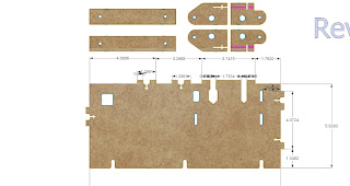
I made a 1", 2", 4", 8" and 10" test pattern and repeated it on the vertical and ran the tests which indicate backlash may be present. My cuts lengths were not exact, so I recalibrated manually moving the steps per unit 1 step at a time till I got the the lengths to come out exactly the same on both X and Y and both are now exactly 1,2,4,8 and 10" as per the SketchUP drawing.
I added some slots in the centers of these test parts and that helped to finally visually show the backlash. It can be seen as the bit entering the foam about 1/32" before where the slot ends up being cut.
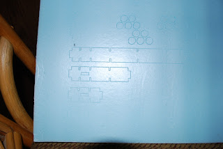
Here is a picture of the test file I was cutting.
I probably need to try to take the stepper out and drill a dimple in the shaft where the set screw is touching the flat of the shaft. I suspect I am still getting a very tiny amount of backlash when the stepper reverses direction and hope by putting the dimple on the shaft that I can once and for all get the pulley to lock in place.
Of course that would mean I will have to go thru all of the adjustments again so I just tightened down the set screw some more without taking the stepper off.

Very consistent.
I guess maybe tomorrow I will drag my wifes computer back out to the shop and play with Mach 3's backlash settings since the backlash code in the Planet-CNC is disabled.
The measured value corresponded very close to my guess of 1/32" (.031).
As the stepper motor is adjusted to take out the slack in the belt, it pulls the two rollers closer together which causes them to no longer be parallel with one another.
Using the Belt Sander example in which adjusting the belt sanders roller causes the sandpaper to skew left or right, the same principle applies here.
I fashioned a new end cap adjuster for the left side which split the adjustment plate into two pieces. John added some angle brackets for finer adjustment.


I drew it up in sketchup and cut it out, but did not actually end up using the holes I had provided along the bottom. I just used the existing bolts and tightened it down and it is holding just fine.
I tried measuring the distance between rollers on both ends to set them exactly the same distance apart on both ends, but I still ended up with skew present. I discovered that if the bit returns to the left of the origination hole, you just need to spread the left end of the rollers apart a bit more and that will move the material back to the right. It only takes a few thousandths, maybe .030 (1/32") to effect a big change, so I loosened the bolt very slightly and just tapped on the one roller to move it in very small increments.
I should also mention, that I had to enlarge the opening (for the hex shaft) on the far side of the left support panel (the one closest to the back of the machine) to give me some room to adjust the play.
I was able to totally eliminate the skew by doing this. Each time I would move it, I would run the bit back and forth along the X axis about 12 inches each way, repeating 4 times, and then would check to see where the bit returned.
Once I had the skew eliminated, I started doing runs using a test file made similar to my EO-Cub wing.
I made a 1", 2", 4", 8" and 10" test pattern and repeated it on the vertical and ran the tests which indicate backlash may be present. My cuts lengths were not exact, so I recalibrated manually moving the steps per unit 1 step at a time till I got the the lengths to come out exactly the same on both X and Y and both are now exactly 1,2,4,8 and 10" as per the SketchUP drawing.
I added some slots in the centers of these test parts and that helped to finally visually show the backlash. It can be seen as the bit entering the foam about 1/32" before where the slot ends up being cut.

Here is a picture of the test file I was cutting.
I probably need to try to take the stepper out and drill a dimple in the shaft where the set screw is touching the flat of the shaft. I suspect I am still getting a very tiny amount of backlash when the stepper reverses direction and hope by putting the dimple on the shaft that I can once and for all get the pulley to lock in place.
Of course that would mean I will have to go thru all of the adjustments again so I just tightened down the set screw some more without taking the stepper off.
I drew up a diagram to help me understand how the Backlash was affecting my cuts. It helped me visualize what the machine was doing and confirmed my theory.

In the test cut above, the slots along the top are supposed to line up with the slots along the bottom, but due to missed steps as the drive rollers change direction, I get about a 1/32" difference in alignment occuring in the parts I am trying to cut and build. This means I cannot fasten the ribs of my wing to the I-Beam without getting out an Xacto blade and opening up the slots on one side or the other so that they line up.
Update: 10 PM
I found this link which showed how to measure your backlash...
I measured my backlash by inputting G1 commands moving the X axis .1" at a time at a feed rate of 1 IPM with a dial indicator on the x axis. Putt, putt, putt, putt..... forward to .5" doing .1" at a time and then back to .4".
I was able to measure a .024 difference every time it reversed direction.
Very consistent.
I guess maybe tomorrow I will drag my wifes computer back out to the shop and play with Mach 3's backlash settings since the backlash code in the Planet-CNC is disabled.
The measured value corresponded very close to my guess of 1/32" (.031).
Sure explains why the EO-Cub Balsa cuts came out the way they did.
Now I can't help but wonder if the original pulleys with the finer teeth would produce less backlash.
Now I can't help but wonder if the original pulleys with the finer teeth would produce less backlash.
Guess, we'll find out when Mark gets the new drive rollers ready.
The Two Step
Texas Two Step has begun. One step forward, two steps back. But before we go there,
Alan Chervitz stopped by the shop yesterday and visited with I and John Bernard.
We discussed everything from Sketchup to building the Phlatprinter \\\ and modding it.
Great guy! We had a good time talking with him.
After he left, I decided to get down to cutting some Balsa which I had been waiting for the day when the machine would do it accurately.
Initially, things looked good, but when I assembled the parts, I found more problems. Appears like the skew problem is back.
Too late last night to look into it, but I started in first light of day today to track it down.
By clamping the rollers at the pulley end toward themselves, I discovered where the skew was coming from.
Pulled the drive rollers out and sure enough, one of the hex shafts that had been epoxied has given way.
Looks like I am going to have to remove the pulley again, see if I can clean out the JB-Weld around the hex shaft, add shims and epoxy it all together again.
While trying to find the problem, I did observe that I could adjust the circles perfectly by clamping the rollers toward themselves, so there is yet one more area in which we need to keep an eye on.
Maybe we can come up with a mod to be able to adjust the roller skew?
Thursday, January 13, 2011
Back to Cutting Again
The JB-Weld Original Epoxy has finally cured. Waiting 24 hours was a drag, but ya gotta do what you gotta do.
The Phlatprinter \\\ is back up and cutting foam once again. Hopefully, the epoxy will take to the nylon this time and I won't need to replace the pulley with the polycarbinate.
As many times as I have had the drive rollers in and out, I think I could do it in my sleep now. It is hardly more than a 5 minute job now. This time my eyeball, "its about right" installation turned out to be within +- .009 across the width of the Y axis.
I took the vacuum dress off. It is a bit too long and clumsy. I may trim it down and try it again later, but I like being able to keep an eye on the bit to see if it is loading up, especially when doing foam where you can heat up the bit and melt the foam if the feed rate and spindle speed are not matched up. With the pause feature, it is easy enough to interrupt the workflow and clear the bit if necessary, adjust the feed rate and resume where you left off.
I have a visitor coming by this morning to checkout the machine and talk CNC.
Then later today, I might start cutting some Balsa for a wing I have been itching to build.
Wednesday, January 12, 2011
Vacuum Dress
I don't know if this will even work, but here it is anyway...
I had some leftover clear heat shrink tubing and some adhesive backed neoprene rubber left over from my PVC roller attempt so I cut some strips of the clear tubing and made a dress for the Bosch Laminate Router attachment. It is just held in place by the adhesive on the rubber strips.

I won't know how this works yet because I want to let the epoxy on the drive roller pulley cure a bit longer before I start putting stress on it.
Then too, I need to make sure the bit won't get caught in the dress when traversing along the Y axis and going up and down on the Z axis whilst the vacuum is sucking away.
There is time for that tomorrow.
Alan Chervitz is dropping in tomorrow to take a look at my setup. Hopefully, it will be up and running by then with the pulley holding on via the new epoxy job.
Arggg! Wrong Pulley - My Fault
The pulleys just arrived. It seems I was not paying attention and ordered the wrong diameter!
It should have been...
The large pulley is part number A 6L 3-28DF03708 and runs $5.38 each.
What I got had an outside diameter of 2.2 inches instead of the 1.7 inches I needed.
So, another order, next day air this time and maybe I will get it right. Dang I hate it when I do something stupid like this.
Now I can only hope the nylon will hold up for a few days more.
Waiting....
The polycarbinate pulleys I ordered are scheduled for delivery this afternoon. The Epoxy is still curing from the rework last night on the nylon versions. I don't have much faith that the epoxy will adhere to the nylon but since they are all I have at the moment, they will have to do.
I may get to do this all over again, but this time I will video it just in case anyone else wants or needs to try it later on their machines.
So while we're waiting, lets talk about MDF and the Phlatprinters.
It seems that some people think that the only thing I am cutting is MDF and that is the reason for my posts on the skew problem so I want to set the record straight.
The multi-pass option and variable feed rates allow us to cut anything so long as we do so in shallow enough cuts as not to impede the flow of material against any of its axis. It was promoted by the PhlatFolks early on and I find it useful for a number of things such as calibrating the machine.
MDF just happens to be easy to cut and has a nice flat surface. A small section of MDF comes in handy to lay across the rollers and then use it to calibrate your Z axis with a dial indicator for example.
I also like to use it when calibrating the X axis because it provides a nice clean hard edge for which to get an accurate measurement with either a tape measure or digital caliper.
Most of the time I will be cutting foam, but during the setup phase, 1/4" MDF has proven to be a good way to test my setup. It has almost zero drag in the sizes I am using since it rides on top of the rollers and does not even touch the top of the cabinet. It gives me a good surface for which to get measurements taken.
When I used 1/2" foam to do some of the same tests I have been doing, I found the foam introduced a drag into the equation that put additional load on the stepper and could introduce errors due to that drag.
So MDF has become a standard item in my toolkit, but foam will be the main thing I will be cutting once the machine is up and running to my satisfaction.
I have some ideas for a new dust shield. Maybe I will have something to demonstrate by tomorrow.
I
Tuesday, January 11, 2011
A Minor Setback
I just had to fool with it... Was checking the height accuracy across the width of the rollers. It was .030 higher on one side. While adjusting it, I must have put too much stress on the J-B Weld on the first roller.
Sure wish my polycarbonite pulleys would get here. The nylon pulleys I got earlier are just not made for gluing.
This time I took Johns suggestion and bored holes all around the inside where the epoxy resides. This should give it a little more strength. This time, I am using the original blend, 24 hour cure stuff, ugggh. Hate waiting for it to cure, but if ya gotta, ya gotta. Just can't seem to take any shortcuts.
Oh well, what's another 24 hours... I know the method works, just need to get the right material in now.
Success At Last!
Using the 4 minute JB-Weld Kwick, I re-attached the nylon drive roller pulley once again and let it cure the recommended 4 hours. Checking the specs on the JB-Weld showed the Kwick version with the same lateral tensil strength as the slow cure stuff so it seems it was a good choice.
I ran my usual back and forth X axis test which drives the rollers over a 12 inch path over and over and returns the bit to the home position. In the past, this is where skew would normally be observed but this time, the bit returned precisely to home position and the material did not skew at all!
I then ran my usually circle tests and noticed a minute amount of dogleg present. More cutting and the dogleg got worse. I realized the X drive stepper set screw was coming loose, so I removed the stepper and installed an allen head hex screw in which I could get a good solid bite on the screw to really clamp down on the stepper shaft.
The next circle test was perfect! No more dogleg, although in the past, using the original stepper pulley with the same modification, I was unable to eliminate it, so I suspect this occurance was simply due to using the new stepper pulley which had not yet been modified.
I am very pleased with the outcome to say the least! It confirms all of my past analysis and solves the mystery which has been so elusive.
I think the 3/8" deeper grooved pulleys will work out much better for several reasons, one being that the steps per unit values of the X and Y are now very similar. This was a problem for the USB CNC software according to Andrej at Planet-CNC.com. The second reason is that the wear I was seeing on the old stepper pulley was significant and it had very few hours on it. To compound the issue, when MDF was being cut, the dust would settle in between the grooves of the stepper pulley and harden which reduced an already shallow area for the belt to grab onto.
Depending on the interest from Phlatforum users, I would be willing to put together a video showing exactly how I cut the old pulleys off the drive rollers and how I attached the new ones.
Putting it down in words doesn't convey the topic nearly as well as seeing it done.
Now that I finally have a working machine, I can get back to completing some projects that have been put on hold.
Be sure to check out my blog for updates. I will be posting some additional articles on how to upgrade the Phlatprinter \\\ with some some different components that should provide some added value to it in the coming days. This includes swapping out the X axis stepper motor for a larger capacity one, replacing the Easy-CNC controller with a Gecko G540, replacing the spindle drive with a high speed laminate router, more details on replacing the drive roller pulleys with 3/8" pulleys, and a little bit on configuring the USB Planet-CNC software and some caveats to be on the lookout for.
Drive Roller Mod First Test
For a short while, I was actually cutting a circle that looked like a circle!
Until my JB Weld bond broke that is...
It was my own fault. The first roller I experimented with, I used Aileens Tacky glue to try to hold the pulley in place and then I applied the JB Weld to the outter edges of the pulley. That of course did not hold, so I applied the JB Weld to the whole surface of the pulley and by now had figured out how to accurately position it, but in my haste, I neglected to clean the old tacky glue from the pulley!
How stupid on my part!
I am also using nylon pulleys because the polycarbinate pulleys I ordered last week have not yet arrived. This material is not conducive to gluing in the first place.
So anyway, the pulley separated with a nice clean break and I am now going to try the JB Weld Kwick which is not as strong as the original JB Weld, but it will cure in only 4 hours vs the 15 to 24 hours that would be required of the stronger JB Weld.
This may fail of course, but at least I should know the results soon and if necessary, I will just do it again with the right epoxy next time.
I am not too concerned about longevity at this point. I will want to use the polycarbinate pulleys when they come in anyway.
The exciting part is that from the short time I was able to run some tests, the results were positive for a change!
The bit returned precisely to home after doing 10 itterations of moving the X axis 22 inches back and forth and there was zero skew, proving what I have been saying all along.
All this on just one attempt to position the rollers in the machine and I just eyeballed the rollers this time, no calipers, no special tools, just "that looks about right". Quick and dirty.
The 2" circle had a very slight dogleg, almost undetctable which I think can be eliminated with a more accurate calibration of both the X and Y axis. Again, I kind of rushed it this time, wanting to see if there was improvement of the skew problem and was planning on doing a more accurate calibration once those tests were complete but the pulley gave way before I could do that.
My next report should be later this afternoon if all goes well with the lighter weight epoxy, otherwise we are looking at Wednesday afternoon before the next test can begin.
Monday, January 10, 2011
Repairing a Drive Roller
Before I forget, I want to thank John Bernard, my friend who lives just a few miles up the road from me.
Without his help and guidance, I would not have gained the knowledge I am able to present here.
Okay, so we know where the skew forms. This post will explain how to fix it.
The first step in the process is to remove the pulleys from the drive roller. While you're at it, you might want to first order a new set to replace them with.
My recommendation is to use a 3/8" pulley with deeper teeth in place of the existing set. This will require a new stepper pulley as well as a new belt.
The reason I recommend the larger pulley is because the fine teeth on the existing ones can clog up with MDF dust as you get into cutting harder material than just foam. The existing pulleys can easily jump a tooth because of the shallow grooves in them.
I get my pulleys from this website https://sdp-si.com/eStore/
The pulley we want is an XL series pulley. You will want to pick up a 12" and 13" belt for them. You can probably just get the 13" belt, but I ordered two sizes just in case one was a little short.
The large pulley is part number A 6L 3-28DF03708 and runs $5.38 each.
The stepper pulley is replaced by a larger one, part number A 6Z 3-12DF03708 which sells for $6.71. I would recommend a smaller OD version, but the two smaller ones under this one are out of stock.
The 13" belt is part number A 6B 3-065037 and is $5.78
Okay, so now that you have the parts ordered, cutting the old pulley off the drive roller is the next step.
I made some simple V blocks to hold the roller and used a diamond blade cuter in my Dremel tool to quickly cut the old pulley off the roller as I manually rotated the drive roller in the V block.
The next step is to measure the actual amount of slop in your Hex Shaft.
Using clamps, clamp the roller to a table top and use a dial indicator (available from Harbor Freight for about $12) to get a reading when the hex shaft is at its lowest point.
With your fingers, push up on the hex shaft till it touches the top of the bearing race. Measure the distance traveled. In my case it was .015.
Next, you need to shim the hex shaft with a toothpick or sliver of wood or carbon fiber to split the difference (.0075).
Mix up some JB Weld Kwick (4 minute Epoxy) and put a small amount in between the hex shaft and the bearing race with a toothpick. Don't touch anything until this has setup, then do the opposite end the same way.
When both pieces have been completed, mix up some JB Weld Original and go around the entire outside bearing race filling in between the hex shaft and the race. Let this cure for 24 hours without disturbing it! Your Hex Shaft should now be centered and will be used to ensure the pulley that is attached in the next steps will be centered as well.

When the new pulley arrives, you will use JB Weld to reattach it, but first you will need to cut the center out of the pulley so that it fits over the end of the drive roller. Again, the trusty Dremel tool comes in handy for this. I put a 1/16" mill bit from my Phlatprinter bit kit into the Dremel tool and just slowly carve out the center. Be careful! You may want to lock the pulley down in a vice (protected with a rag or rubber of course) so that it does not slip while you mill it out.
You will need a set of digital calipers for the next step. Lowes has them for about $30.

Once you have the pulley prepared, clean the surface of the drive roller and make sure it is flat. Sand it down if necessary. Mix up two parts evenly of JB Weld Original Epoxy. Spread it on the back side of the pulley and place it on the end of the roller where you removed the old pulley.
Set the calipers to 1.095" and place one edge on one face of the Hex Shaft. The other end of the caliper should fit over the edge of the pulley. If not, position it so it does. Then rotate the caliper and hex shaft around the edge of the pulley, several times, adjusting the pulley in place so that when done, all sides of the pulley are accurately spaced the same distance.
When you have the pulley centered well, stand the roller on end where it can set undisturbed for the next 24 hours. Allow the epoxy to fully cure before putting back in your Phlatprinter \\\.
Now that the hex shaft is locked to the roller, you will only need two lock collars to hold the roller in place. You will not need any spacers, just position the roller so that the inside of the pulley is just past the MDF and align the new stepper pulley so that the belt centers on them and lock down the hex shaft with the two lock collars.
Your X axis calibration will have to be changed. With the new pulleys, your calibration values will decrease by about half, in the 500 range.
In follow up posts, I will explain how to calibrate your X axis, but you should already know how to do that by now I would expect.
Without his help and guidance, I would not have gained the knowledge I am able to present here.
Okay, so we know where the skew forms. This post will explain how to fix it.
The first step in the process is to remove the pulleys from the drive roller. While you're at it, you might want to first order a new set to replace them with.
My recommendation is to use a 3/8" pulley with deeper teeth in place of the existing set. This will require a new stepper pulley as well as a new belt.
The reason I recommend the larger pulley is because the fine teeth on the existing ones can clog up with MDF dust as you get into cutting harder material than just foam. The existing pulleys can easily jump a tooth because of the shallow grooves in them.
I get my pulleys from this website https://sdp-si.com/eStore/
The pulley we want is an XL series pulley. You will want to pick up a 12" and 13" belt for them. You can probably just get the 13" belt, but I ordered two sizes just in case one was a little short.
The large pulley is part number A 6L 3-28DF03708 and runs $5.38 each.
The stepper pulley is replaced by a larger one, part number A 6Z 3-12DF03708 which sells for $6.71. I would recommend a smaller OD version, but the two smaller ones under this one are out of stock.
The 13" belt is part number A 6B 3-065037 and is $5.78
Okay, so now that you have the parts ordered, cutting the old pulley off the drive roller is the next step.
I made some simple V blocks to hold the roller and used a diamond blade cuter in my Dremel tool to quickly cut the old pulley off the roller as I manually rotated the drive roller in the V block.
The next step is to measure the actual amount of slop in your Hex Shaft.
Using clamps, clamp the roller to a table top and use a dial indicator (available from Harbor Freight for about $12) to get a reading when the hex shaft is at its lowest point.
With your fingers, push up on the hex shaft till it touches the top of the bearing race. Measure the distance traveled. In my case it was .015.
Next, you need to shim the hex shaft with a toothpick or sliver of wood or carbon fiber to split the difference (.0075).
Mix up some JB Weld Kwick (4 minute Epoxy) and put a small amount in between the hex shaft and the bearing race with a toothpick. Don't touch anything until this has setup, then do the opposite end the same way.
When both pieces have been completed, mix up some JB Weld Original and go around the entire outside bearing race filling in between the hex shaft and the race. Let this cure for 24 hours without disturbing it! Your Hex Shaft should now be centered and will be used to ensure the pulley that is attached in the next steps will be centered as well.
The picture below shows the V block and a dial indicator used to measure the slop in the Hex Shaft.

When the new pulley arrives, you will use JB Weld to reattach it, but first you will need to cut the center out of the pulley so that it fits over the end of the drive roller. Again, the trusty Dremel tool comes in handy for this. I put a 1/16" mill bit from my Phlatprinter bit kit into the Dremel tool and just slowly carve out the center. Be careful! You may want to lock the pulley down in a vice (protected with a rag or rubber of course) so that it does not slip while you mill it out.
You will need a set of digital calipers for the next step. Lowes has them for about $30.

Once you have the pulley prepared, clean the surface of the drive roller and make sure it is flat. Sand it down if necessary. Mix up two parts evenly of JB Weld Original Epoxy. Spread it on the back side of the pulley and place it on the end of the roller where you removed the old pulley.
Set the calipers to 1.095" and place one edge on one face of the Hex Shaft. The other end of the caliper should fit over the edge of the pulley. If not, position it so it does. Then rotate the caliper and hex shaft around the edge of the pulley, several times, adjusting the pulley in place so that when done, all sides of the pulley are accurately spaced the same distance.
When you have the pulley centered well, stand the roller on end where it can set undisturbed for the next 24 hours. Allow the epoxy to fully cure before putting back in your Phlatprinter \\\.
Now that the hex shaft is locked to the roller, you will only need two lock collars to hold the roller in place. You will not need any spacers, just position the roller so that the inside of the pulley is just past the MDF and align the new stepper pulley so that the belt centers on them and lock down the hex shaft with the two lock collars.
Your X axis calibration will have to be changed. With the new pulleys, your calibration values will decrease by about half, in the 500 range.
In follow up posts, I will explain how to calibrate your X axis, but you should already know how to do that by now I would expect.
Subscribe to:
Posts (Atom)